Definition/Introduction
Understanding what a lens is first requires understanding what light is. Light is electromagnetic radiation that exhibits properties of both waves and particles.[1] It is currently understood to be composed of particles called photons. The path along which a photon travels is often called a “light ray.” It is the wave-particle duality that explains the way light travels. Much like a particle, photons travel in a linear direction when uninterrupted. However, much like a wave, light rays can also be diffracted and refracted.[1] Lenses are the objects that refract light rays and are the focus of this topic.
A given object is visualized when light rays travel from a principal light source (the sun, light bulbs in a room, etc), bounce off the atoms on that object’s surface, and eventually travel into the human eye. The cornea and lens focus the light rays onto the retina, which contains a dense grid of photoreceptor cells that detect these light rays.[2] The same phenomenon occurs with a camera with a lens that focuses the light onto a dense grid of photoreceptor chips.
To understand lenses, 1 must understand that light rays bounce off objects (as small as a single atom) in all directions in a well-lit setting. Of all these nearly infinite light rays, those that come in contact with a lens have their direction of travel bent or “refracted.” See Diagram. Schematic of a Lens Refracting Light. This ultimately leads to the ability to recreate images of objects. Pictures are made when images are recreated on film or a grid of photoreceptors. Vision results when images are recreated on the retina in the back of the eye. Lenses make all of this possible.
Issues of Concern
Register For Free And Read The Full Article
 Search engine and full access to all medical articles
- 10 free questions in your specialty
- Free CME/CE Activities
- Free daily question in your email
- Save favorite articles to your dashboard
- Emails offering discounts
Learn more about a Subscription to StatPearls Point-of-Care
Issues of Concern
Terminology
- Medium - an object through which a wave passes, in this case, light. This could be air, glass, water, etc.
- Refraction - the phenomenon of a lens changing the direction in which light rays travel
- Lens (natural or biological and synthetic) - an optical device or system that refracts light
- on a single side of a lens, which can be convex, concave, or plano. A lens where both sides are convex or concave is called a "biconvex" or "biconcave" lens, respectively. A lens where the radius of curvature for both sides is the same is called an "equiconvex" or "equiconcave" lens.
- Optical axis - an imaginary line that passes through the center of a lens, perpendicular to the lens' surface
- Collimated Rays - light rays that travel parallel to the optical axis of a lens
- Focal Length - the length from the center of a lens to the point on the optical axis through which all collimated light rays are refracted
- Focal Point - the point marking the focal length on the optical axis
- Lens Power - the reciprocal of the focal length of a given lens. See Diagram. Terminology Associated With Lens Optics
Lens Function
A lens functions to recreate an image of an object by refracting the light coming off that object. Lenses refract any light that passes them at a non-perpendicular angle (Figure 2). The degree of refraction depends on the medium of the lens and the medium through which the light travels on either side of the lens, typically air. It also depends on the angle at which the light ray penetrates the lens. The degree of refraction can be calculated with Snell's Law:
n1sinθ1 = n2sinθ2
where n represents the refractive index for that medium and θ represents the angle of incidence.[3]
Light is refracted because it travels at different velocities in different mediums and maintains the same frequency. This phenomenon of maintaining the same frequency is why blue light still appears blue, whether traveling through air, water, glass, or any other medium. Light rays are refracted as they enter a lens and exit the opposite side. The introductory study of optics often assumes that light rays are only refracted once as they pass through a lens and not twice. This is what would happen if a lens had a width of zero. This fictional concept of a perfectly thin lens is often called the "thin lens" assumption, and utilizing it removes a phenomenon called "spherical aberration," which is discussed later in the topic.[4] The focal length (and optical power) of a lens can be calculated with the lensmaker's equation:
Optical power = 1/f = ((nlens - nsurroundings)/nsurroundings)((1/R1) - (1/R2) + (d(n - 1)/(nR1R2)))
Where n is the index of refraction of the lens material or its surroundings, R1 is the radius of curvature of the side of the lens the light rays first enter, R2 is the radius of curvature of the side of the lens that the light rays exit, and d is the lens' thickness. When a thin lens is assumed, and the medium surrounding a lens is air (with an index of refraction of 1), the lensmaker's equation can be simplified:
Optical power = 1/f = (n - 1)((1/R1) - (1/R2))
In a well-lit setting, infinite light rays bounce off an object and then pass through a nearby lens. Despite this overwhelming quantity, studying 3 of these rays in a two-dimensional plane helps us understand how lenses function.[5] Using these 3 light rays and the thin lens assumption creates a good model for understanding how lenses function to reconstruct images.
Convex Lens Model with an Object Beyond the Focal Point
The model begins with a small object (a single atom, for example) located at a distance do from a lens (where d is greater than the focal length) and a height ho from the optical axis (where h is less than half the height of the lens). The first of the 3 light rays to consider coming from this object is the 1 that travels straight through the center of the lens. Light rays that travel through the center of a thin lens do not get refracted so that a straight line can be made. The lack of refraction is not because it penetrates the lens at a perpendicular angle but rather because however much it gets refracted 1 way as it enters the lens, it gets refracted just as much back the other way as it leaves the other side. With a thick lens, the ray's path would still be interrupted. But with the thin lens assumption, the ray travels through in a perfectly straight line. This is illustrated by line 1 in Figure 3. The second light ray to consider travels parallel to the optical axis. Since it travels parallel to the axis, it is a collimated ray, and all collimated rays are refracted by convex lenses such that they pass through the focal point on the opposite side of the lens. This is illustrated by line 2 in Figure 3. The third line travels through the focal point on the same side of the lens as the object. This line is refracted to travel parallel to the optical axis on the opposite side of the lens, becoming a collimated ray. As all 3 of these rays are considered, it is noted that they all converge at a single point on the opposite side of the lens. Assuming a thin lens and an object as small as an atom, every single light ray coming off the small object and traveling through the lens passes through this same single point, as illustrated by the column on the left in Figure 3. This convergence of light rays results in a reconstructed image of the object.
This reconstructed image is termed a "real image" because the viewer does not have to look through the lens. The image is not a hologram, meaning it does not appear suspended in the air. A solid, white backdrop is required at the location of the image for it to be visualized. But with such a backdrop, the image of the small object is just as visible as the object itself. When dealing with a convex lens, real images always result when the object is further than the focal point.[6] Additionally, real images always appear on the opposite side of the lens as the small object and always on the opposite side of the optical axis. If the small object is located at twice the distance from the lens as the focal length (do = 2f), then the real image of the object also appears at a distance twice that of the focal length on the opposite side of the lens (do = di = 2f). Additionally, the image is the same size as the small object, appearing the same distance from the optical axis but on the opposite side (ho = -hi). If the small object is located at a distance other than twice that of the focal length (do ≠ 2f), then the size of the image, its distance from the lens, and its distance from the optical axis differ from that of the object. These values can be calculated by the thin lens equation:[7]
1/f = 1/do + 1/di
By convention, the focal length is always given a positive sign for converging lenses and a negative sign for diverging lenses. For this reason, convex lenses are often called "positive lenses." Looking at the thin lens equation, di is always positive to complete the equation if do > f. A positive value for di is another way to tell that an image is real.
Convex Lens Model with an Object Closer than the Focal Point
The steps for constructing the 3 significant light rays in a two-dimensional model differ slightly for objects closer to the convex lens than the focal length. The first light ray can be constructed similarly to the first line in the model with an object beyond the focal length. The ray travels from the small object and through the center of the thin lens without being refracted. This is represented by line 4 in the diagram. Where the construction of the ray differs in this model is that the ray also needs to be constructed in the other direction, past the object, traveling away from the lens. This ray is imaginary since it is not the same as the light traveling through the lens, which originates at the object itself. A dashed line is used to indicate that this ray is imaginary. The second light ray travels parallel to the optical axis again, making it a collimated beam. It gets refracted such that it passes through the focal point on the opposite side of the lens. However, it can now be noted that this light ray and the first light ray never converge. Such is the case whenever the small object is closer to a convex lens than the focal point. In the model, an imaginary ray is also constructed for this ray. This is represented by the dashed line in the diagram traveling as a continuation of line 5 through the lens. Note that this imaginary ray continues the second ray after it is refracted and not before. This is because that is the ray that a viewer sees when looking through the lens from the opposite side of the object. It can be seen that while the refracted light rays never converge, the imaginary rays do.
The third ray in the model again travels through the small object and the focal point on 1 side of the lens. It is then refracted to travel parallel to the optical axis on the opposite side of the lens, becoming a collimated ray. As with the second line, an imaginary line is constructed as a straight continuation of the refracted ray. This imaginary ray also passes through the same convergence point as the first 2 rays, as illustrated in the diagram. See Diagram. Ray Diagrams for Different Lenses and Objects at Different Distances. Once again, with the assumption of a thin lens and an object as small as an atom, all light rays that travel off the object and through the lens converge at a single point to create an image. The difference here is that now it is the imaginary continuation of the refracted light rays that converge, not the light rays themselves. This creates a virtual image and not a real image. See Diagram. Lens Refracting all Light Rays Coming From an Object to Create a Real Image). The virtual image can only be seen when the viewer looks through the lens, hence why it is called "virtual."
An example of virtual images is the use of a magnifying glass. Magnifying glasses are convex lenses. When in use, the magnifying glass must be held close to the object being viewed so that the object is closer to the magnifying glass than its focal length. Then, a virtual image is made upright, magnified, and only visible when the viewer looks through the lens. When dealing with convex lenses, virtual images always result when the object is closer to the lens than the focal point.[6] Additionally, the virtual image always appears on the same side of the lens as the small object and always on the same side of the optical axis. The thin lens equation can once again express the distance between both the image and the object from the lens:
1/f = 1/do + 1/di
Once again, looking at the thin lens equation, it is noted that with a positive value for f for a convex lens, di has to be negative if do < f, indicating the image is a virtual image.
Concave Lens Model
With concave lenses, 3 simple rays can again be used to show the location of an image. Once again, the first ray passes straight through the center of the lens. This ray would get refracted 1 way upon entering the lens and then refracted equally the other way upon exiting the lens. With the thin lens assumption, this is equivalent to a straight line passing through the center of the lens without any refraction. This is represented by line 7 in the diagram. The second of the 3 simple rays starts as a collimated ray, traveling from the object to the lens parallel to the optical axis. Since concave lenses diverge light, this ray does not get refracted to pass through the focal point but rather so that its imaginary continuation passes through the focal point on the same side of the lens as the object. This is illustrated by line 8 in Figure 3. The third ray travels towards the focal point beyond the lens but does not reach it because it gets refracted to become a collimated ray beyond the lens. The imaginary continuation of this light ray travels parallel to the optical axis on the same side of the lens as the object. This is illustrated by line 9 in the diagram. As with convex lenses and an object closer to the lens than the focal point, all imaginary lines merge at a single point (right column of Figure 3). This single point is a construction of a virtual image that can only be seen as viewers look through the lens. These same 3 simple light rays can be drawn similarly with concave lenses, regardless of the object's distance from the lens. The thin lens equation can once again express the distance between both the image and the object from the lens:
1/f = 1/do + 1/di
This time, looking at the thin lens equation, it is noted that with a negative value for f for a concave lens, di has to be negative, indicating the image is a virtual image. This stands true for all values of do, which is always positive by convention.
Reconstruction of Entire Images
An important aspect to remember when learning about the reconstruction of images is that this phenomenon illustrated above with a single atom occurs with every atom on the surface of an object whose light rays can reach the lens. The diagram provides a visual illustration of this happening with several atoms on the surface of an object instead of just a single atom, as all the other figures have illustrated.
Magnification
One aspect of real and virtual images that the thin lens equation does not calculate is the image's size to the object's size. One of the most powerful uses of lenses is not just to reconstruct images of objects but to magnify (or minimize) those images. The magnification of an image can be calculated by:
M = hi/ho = -di/do
Where M is the magnification (how many times larger or smaller the image is than the object), ho is the object's height, and hi is the height of the image (see Diagram. Magnification of an Image Created by a Lens).[5]
Two-Lens Systems
If 2 lenses are placed immediately next to 1 another, then with the thin lens assumption, the total optical power equals the sum of their optical powers. If there is a distance between the 2 lenses, then calculations of the images made by the 2 lenses can be made using calculations for 1 lens at a time. The image created by the first lens is then treated as the object for the second lens.[5]
Aberration
It should be noted that while these calculations do stand with the theoretical thin lens model, the refraction of light is not as perfect with real lenses. In reality, several phenomena occur that distort the images created by lenses. These phenomena are discussed in more detail in articles on aberration, while only a summary of each is included here. One of the most common of these phenomena is spherical aberration. Spherical aberration refers to the distortion of images that occurs when lenses have spherical sides to them, but the lenses themselves are not thin. When light rays get refracted not once (as with the thin lens assumption) but twice (once on each side of the lens), light rays that pass through the center of a thick lens are refracted differently than light rays that pass through the periphery. Remarkably, the human lens can correct this aberration to a significant degree. This is possible because the lens has a slightly different composition at different layers. This means that the index of refraction is not uniform but rather dynamic across different layers. This change in refraction causes light to be refracted more evenly throughout despite its spherical shape and thickness.[8]
Chromatic aberration is another phenomenon that prevents the formation of perfect images. Chromatic aberration occurs because light rays of different colors have different frequencies, and some frequencies refract more than others, even when the lens and angle of incidence are kept constant. Yet another phenomenon is described by the Petzval field curvature. In the models used in this topic, objects in a single, 2-dimensional plane perpendicular to the optical axis have yielded images also in a 2-dimensional plane perpendicular to the optical axis. However, in reality, spherical lenses tend to create images on a curved plane for objects with a flat plane. The natural curvature of the retina in the human eye corrects this phenomenon to a significant degree. Defocus is another type of aberration. It results when light rays from a single point on an object do not meet at a single point on the image backdrop, meaning the image is simply out of focus. This is typically corrected by adjusting the distance from the lens to the object, the distance from the image to the object, or the lens's focal length. However, it can also be corrected by decreasing the aperture size.
The aperture size is the surface area light can pass in the optical system. In the human eye, the pupil is the aperture size. This concept explains why pinholes are used in the clinical setting. As a pinhole is placed over a patient's eye, the aperture size is made so small that only light rays nearly parallel to the optical axis can make it through, light rays that don't need to be refracted to come into focus on the retina. If patients with blurry vision can see clearly when covering an eye with a pinhole, then their blurry vision is likely due to refractive error as opposed to other pathology.[9]
Clinical Significance
The natural lens found in the human eye allows the eye to perform its function; just as the convex lenses discussed above project real images onto a film or white background, the lens in the human eye (along with the cornea) projects real images onto the retina. Then, photoreceptor cells called "rods" and "cones" detect the focused light and send signals to the brain's visual cortex. There are 2 main points at which the human eye refracts light to focus it on the retina. The cornea first refracts light, which performs most of the eye's total refraction. More technically, light is first refracted as it enters the tear film, the thin layer of moisture resting on the cornea's outer surface. Temporary insufficiency of this layer can lead to improper refraction of light and blurry vision, so patients should be instructed to blink often when measuring visual acuity.[10]
The cornea has a convex shape, leading to tremendous convergence of the light that enters it. However, it should be noted that while the light that enters the eye does pass through various mediums, it does not pass through the air again at any point in its course toward the retina. Therefore, the cornea differs from lenses in that the medium occupying its posterior surface differs from the medium anterior to it. The cornea provides about two-thirds of the eye's total optical power, while the natural lens provides the other third.[4] The human eye contains a natural lens, much like the lenses discussed in this topic, which rests immediately posterior to the pupil. The human lens is biconvex in shape but not equiconvex, with the posterior surface having a greater spherical component than the anterior surface. One particularly unique feature of the human lens is that it can change its shape considerably, changing its focal length. This focal length change allows images of different distances to be focused on the retina with clarity.[8]
Cameras perform this same function but move lenses forward and backward along the optical axis instead of changing shape. The ciliary muscle in the eye suspends the lens posterior to the pupil via ciliary zonules. This muscle contracts and relaxes to make the lens more or less spherically shaped, respectively. The human lens becomes more spherical when viewing images closer to the eye. For visualization of objects close to the eye, greater convergence of light is needed. This is because objects closer to the eye emit light rays that reach the eye's lens axis with greater angles of incidence than objects further from the cornea, as shown in Figure 6. By taking on a more spherical shape, the lens's focal length is reduced (its power increases), allowing for the increased convergence necessary. Likewise, when visualizing objects further from the eye, the lens takes on a less spherical shape, thus increasing its focal length and converging light less.[11]
The lens's shape change is accomplished by the action of the ciliary muscle, a circular muscle that forms a ring around the lens. The proposed mechanism currently most widely accepted is the theory of Helmholtz. This theory states that when the ciliary muscle relaxes, its diameter increases, causing it to pull on the zonules, which in turn pull on the outer rim of the lens to flatten it out. Then, when the ciliary muscle contracts, its diameter decreases, and the tension on the zonules and the lens decreases, allowing it to take on a more spherical shape.[12] Emmetropia occurs when the lens is shaped so objects at an infinite distance are focused on the retina.[13] Suppose an object is located on the optical axis at an infinite distance. In that case, that means that the object is located in the center of the visual field, and all light rays coming off of this object are collimated rays. As discussed in previous sections, collimated rays converge at the focal length. Therefore, to bring objects located an infinite distance from the eye into focus on the retina, the combined focal length of the cornea and lens needs to be equal to the eye's axial length. When this occurs, an eye can see all objects at an infinite distance and is said to be an "emmetropic" eye.
In the clinical setting, this phenomenon occurs for all objects located approximately 2 meters from the eye or further. That is to say, objects located as close as 2 meters from the eye are far enough away that all light rays that come off of them can be considered parallel. They focus on the retina when the focal length of the lens and cornea equals the axial length. This means that for patients with presbyopia, if the inverse of the lens power of the eye is equal to the axial length (which can be achieved naturally or with glasses, contact lenses, etc), then all objects located 2 meters and further can be seen clearly, even though the lens no longer can change shape. It isn't until the patient attempts to visualize objects closer than 2 meters that their vision comes out of focus. Emmetropia is typically the refractive goal for patients undergoing cataract surgery with the placement of an intraocular lens because it gives them the greatest depth of field. The depth of field is the range of different depths at which multiple objects can be in focus at once.
Myopia, or nearsightedness, results when the eye cannot properly focus light rays from distant objects on the retina. Even with the lens at the flattest shape, it can be assumed the lens and cornea together still converge light excessively so that light rays from a single point of the object converge in front of the retina (Figure 7). When these light rays reach the retina, they are scattered, creating dull images in various places on the retina instead of 1 sharp, focused image of their point of origin on the object being visualized. However, when viewing near objects, the eye can properly focus them on the retina since near objects require more convergence. This is why patients with myopia can see objects up close clearly but not objects at a distance (Figure 8).[14]
Myopia can have various causes. It can be due to an axial length that is longer than normal, corneal power that is too great, or lenticular power (optical power of the lens) too great. Of these, the most common cause is an axial length that is too long.[15] Changes in the composition of the lens and, thus, its index of refraction explain the myopic shift sometimes seen with cataract development. Previously, presbyopic patients find that they start to get some of their near vision back as they develop cataracts. This results because cataractogenesis leads to an increased index of refraction of the lens, thus increasing its optical power and bringing near images into focus.[16]
Since myopia occurs when light rays converge excessively, it can be treated with concave lenses that diverge the light before it enters the eye (Figure 7).[17] Contact lenses can also accomplish this by changing the shape of the cornea's anterior surface (Figure 7). This change in shape then changes the cornea's focal length, just as the focal length of a convex lens depends on its shape. Contact lenses that give the cornea a flatter shape increase the anterior radius of curvature. According to the lensmaker's equation, this reduces the optical power of the cornea, thus allowing for the correction of myopia. Procedures such as LASIK (laser-assisted in situ keratomileuses) allow surgeons to use a laser to reconstruct the shape of the cornea so that it can converge light properly, just as it would when wearing contact lenses.[18]
Hyperopia, or farsightedness, is the opposite case of myopia. It results when the eye can focus light rays from distant objects on the retina but not light rays from close objects. Even when the lens takes on its most spherical shape, its combined refractive power and the cornea's combined refractive power are insufficient to sufficiently converge light rays from close objects. Instead of light rays from near objects converging on the retina, they converge behind it (Figure 7).[19] This results in an ability to see distant objects clearly while close objects appear blurry (Figure 8). Hyperopia can have various causes. It can be due to an axial length shorter than normal, corneal power too little, or lenticular power (optical power of the lens) too little. Of these, the most common cause is an axial length that is too short.[15]
Since hyperopia occurs when light rays aren't converged enough, it can be treated with convex lenses that converge light before it enters the eye (Figure 7). In a similar fashion, contact lenses that give the cornea a steeper curvature increase the optical power of the cornea and are prescribed for hyperopia (Figure 7). As with myopia, procedures such as LASIK allow surgeons to use a laser to reconstruct the shape of the cornea, such that it can then converge light properly, just as it would when wearing contact lenses.[20] Presbyopia occurs when the lens hardens and loses its ability to change shape. This results in an ability to see objects clearly at some distances but not at others. Most often, the lens ends up stagnant in its less spherical form, allowing for distant objects to be seen clearly but not close objects. This loss of the lens's ability to change shape is not considered pathologic but a normal aging process.[21] This is why many aging patients hold objects farther away from their eyes to read them and ultimately need reading glasses.
Astigmatism occurs when the cornea (less commonly, the lens) has a steeper curvature in 1 meridian than another.[22] "Meridian" refers to any two-dimensional slice that can be taken through the cornea. Another common way to describe this is that if the cornea's anterior surface is visualized, astigmatism results when the cornea is more oval-shaped than circular. This means that the two-dimensional images reconstructed on the retina could be in focus in 1 dimension while remaining out of focus in another dimension. This can be corrected with glasses that have a cylindrical component to their shape instead of being perfectly spherical.
Nursing, Allied Health, and Interprofessional Team Interventions
Given the high prevalence of refractive errors worldwide, the task of prescribing corrective lenses to those in need can only be accomplished by teams. Eye care personnel typically perform measurements of visual acuity before patients undergo an examination of their eyes. This must be done carefully for the best results from prescription lenses. Patients should be asked to blink often while measuring visual acuity so that the tear film is uninterrupted and the best possible refraction occurs.[10] Refractive errors, while prevalent, are not the only cause of blurry vision. Therefore, upon initial evaluation of refractive errors, a comprehensive eye examination should be performed by qualified providers to rule out other potential ocular pathology and potential causes of blurry vision. The examination should be thorough and include evaluation of the lids, lacrimal glands, conjunctiva, cornea, anterior chamber, iris, posterior chamber, lens, vitreous chamber, and dilated fundus exam. The USPSTF recommends at least 1 comprehensive eye examination on all children aged 3 to 5 years.[23] The American Academy of Ophthalmology recommends that adults under the age of 40 years undergo a comprehensive eye examination at least every 5 to 10 years and more often after that with advancing age.[24]
Media
(Click Image to Enlarge)
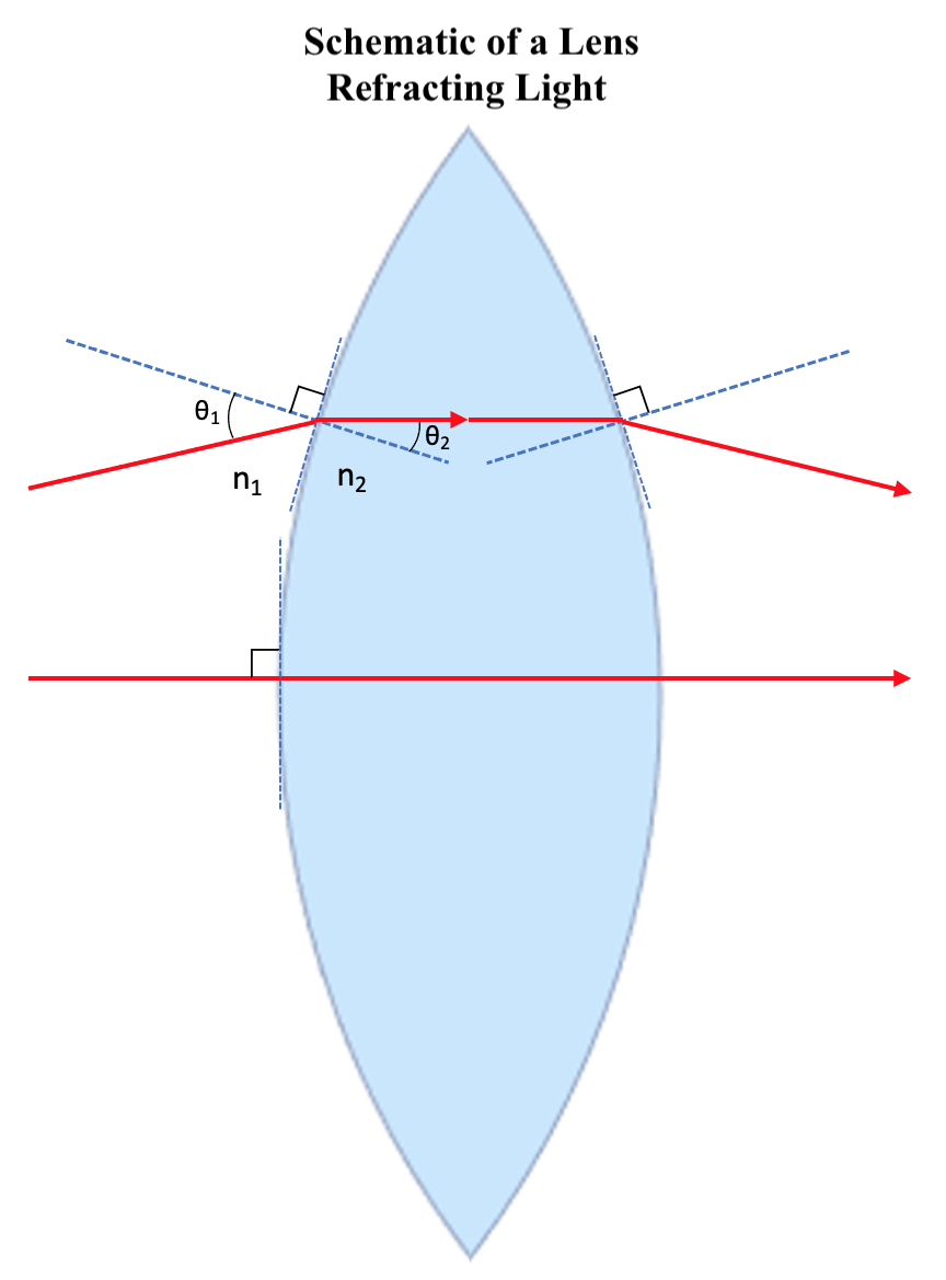
Schematic of a Lens Refracting Light. θ1 represents the angle of incidence as light enters the lens, and θ2 represents the angle of incidence immediately after refraction. Additionally, n1 represents the refractive index for the medium surrounding the lens (typically air), and n2 represents the refractive index for the lens itself. The relationship of these variables is given by Snell Law.
Illustrated and contributed by S Tenney
(Click Image to Enlarge)
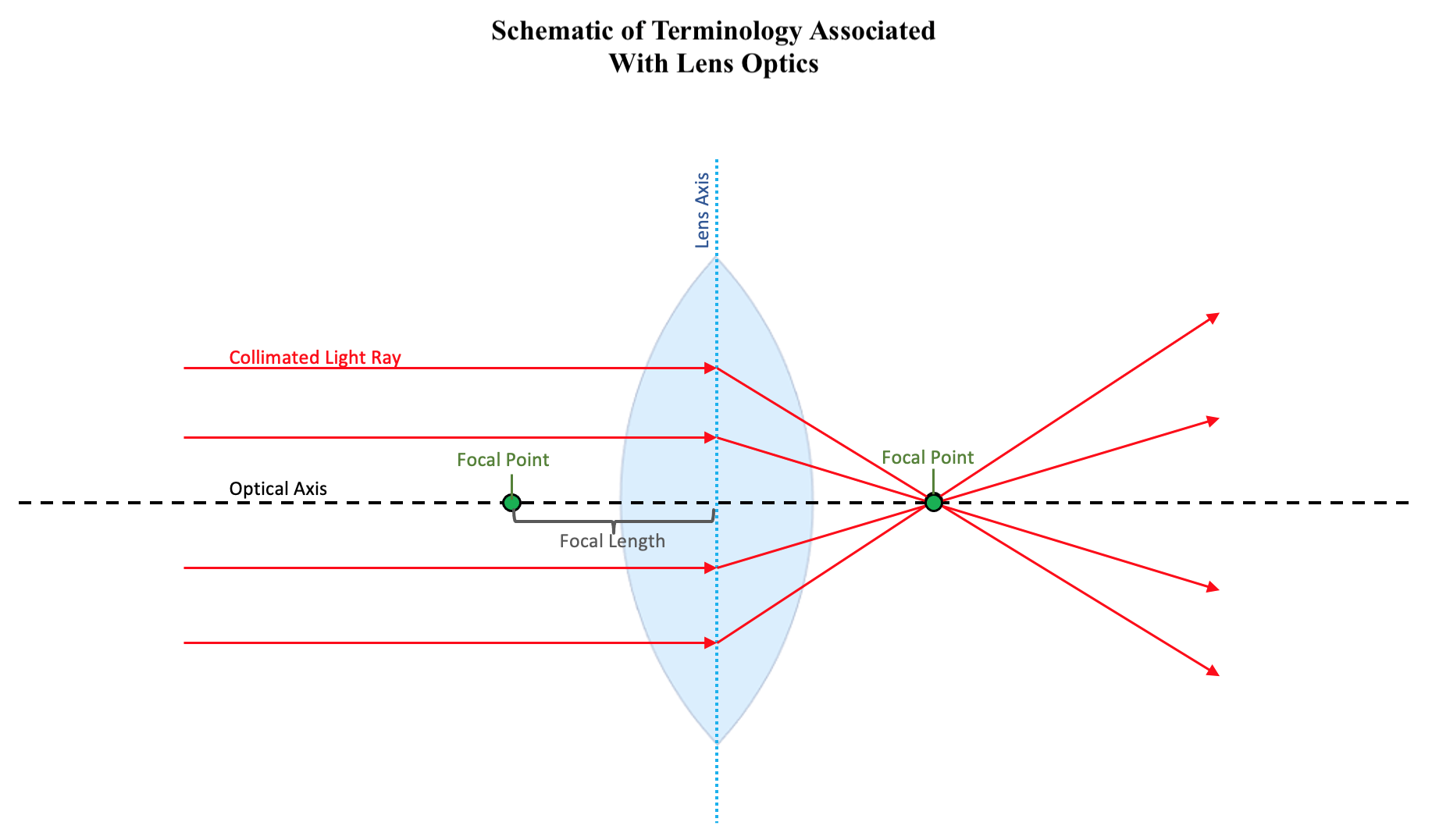
Terminology Associated With Lens Optics. The schematic illustrates optical axis is the imaginary axis that passes through the center of the lens, perpendicular to the surface. The lens axis is the imaginary plane that passes through the center of the two sides of the lens, perpendicular to the optical axis. Collimated light rays are those which travel parallel to the optical axis. The focal point is the point on the optical axis through which all collimated light rays are refracted. The focal length is the distance between the lens axis and the focal point.
Illustrated and contributed by S Tenney
(Click Image to Enlarge)
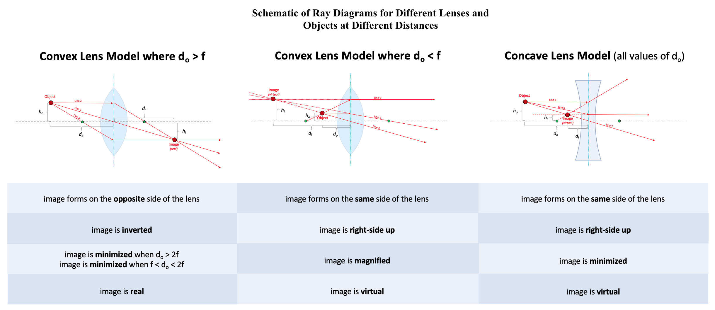
Ray Diagrams for Different Lenses and Objects at Different Distances. For each diagram, do represents the distance from the lens axis to the object's location over the optical axis, while di represents the same for the image of the object created by the lens. Additionally, ho represents the shortest possible distance (height) from the object to the optical axis, while hi represents the same for the image of the object created by the lens. The black dashed lines represent the optical axes, while the blue dotted lines represent the lens axes. The green circles on the optical axes mark the focal points. The thin lens assumption is used.
Illustrated and contributed by S Tenney
(Click Image to Enlarge)
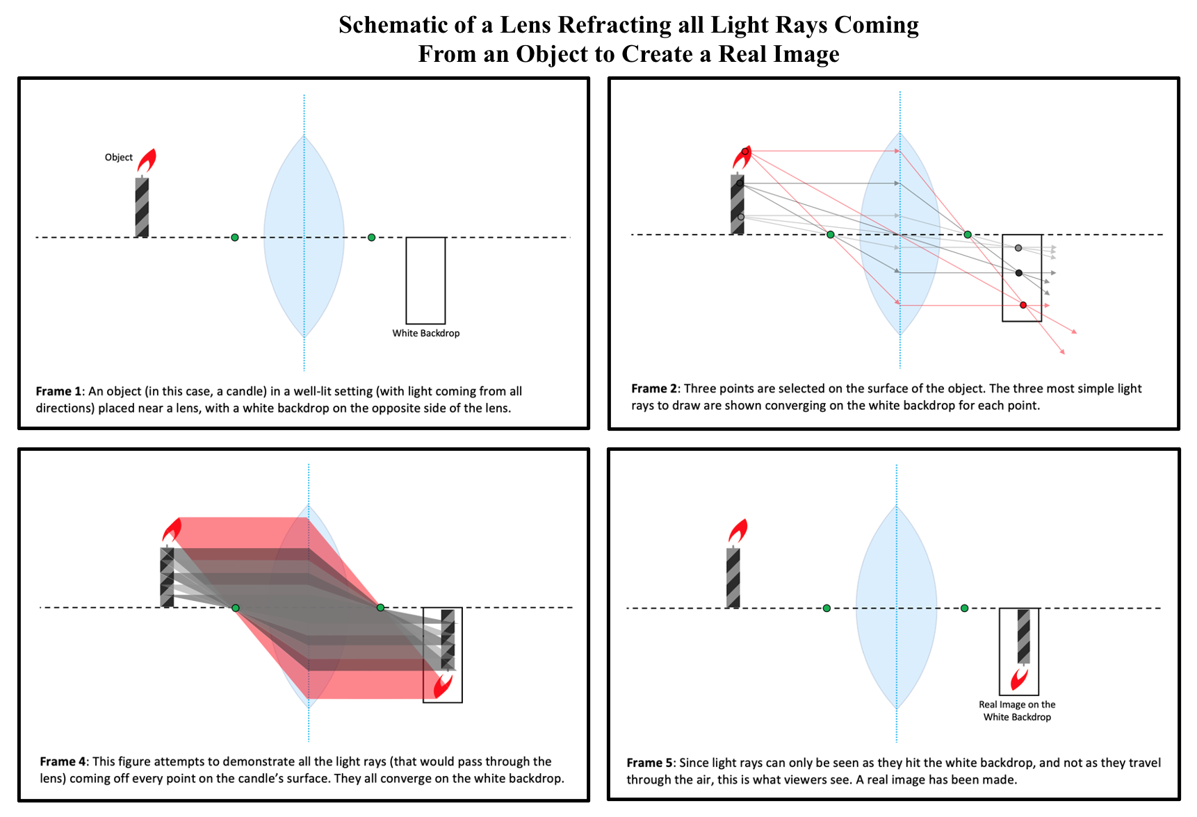
Lens Refracting all Light Rays Coming From an Object to Create a Real Image. In each frame, the candle represents the object from which the lens recreates an image. The black dashed lines represent the optical axes, while the blue dotted lines represent the lens axes. The green circles on the optical axes mark the focal points. The thin lens assumption is used.
Illustrated and contributed by S Tenney
(Click Image to Enlarge)
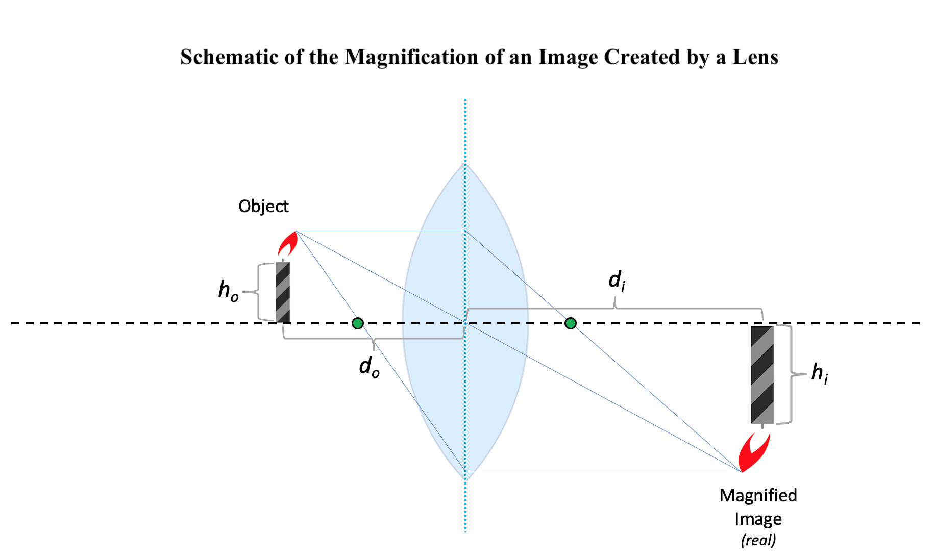
Magnification of an Image Created by a Lens. In this schematic, do represents the distance from the lens axis to the object’s location on the optical axis, while di represents the distance from the lens axis to the image’s location on the optical axis. Additionally, ho represents the height of the object, while hi represents the height of the image.
Illustrated and contributed by S Tenney
References
Sliney DH. What is light? The visible spectrum and beyond. Eye (London, England). 2016 Feb:30(2):222-9. doi: 10.1038/eye.2015.252. Epub 2016 Jan 15 [PubMed PMID: 26768917]
Ludwig PE, Jessu R, Czyz CN. Physiology, Eye. StatPearls. 2024 Jan:(): [PubMed PMID: 29262001]
Ben-Benjamin JS, Cohen L. Equations of motion for rays in a Snell's law medium. The Journal of the Acoustical Society of America. 2015 Feb:137(2):EL171-7. doi: 10.1121/1.4905879. Epub [PubMed PMID: 25698046]
Olsen T. Calculation of intraocular lens power: a review. Acta ophthalmologica Scandinavica. 2007 Aug:85(5):472-85 [PubMed PMID: 17403024]
Maier A, Steidl S, Christlein V, Hornegger J. Medical Imaging Systems: An Introductory Guide. 2018:(): [PubMed PMID: 31725205]
Vangindertael J, Camacho R, Sempels W, Mizuno H, Dedecker P, Janssen KPF. An introduction to optical super-resolution microscopy for the adventurous biologist. Methods and applications in fluorescence. 2018 Mar 16:6(2):022003. doi: 10.1088/2050-6120/aaae0c. Epub 2018 Mar 16 [PubMed PMID: 29422456]
She A, Zhang S, Shian S, Clarke DR, Capasso F. Large area metalenses: design, characterization, and mass manufacturing. Optics express. 2018 Jan 22:26(2):1573-1585. doi: 10.1364/OE.26.001573. Epub [PubMed PMID: 29402031]
Donaldson PJ, Grey AC, Maceo Heilman B, Lim JC, Vaghefi E. The physiological optics of the lens. Progress in retinal and eye research. 2017 Jan:56():e1-e24. doi: 10.1016/j.preteyeres.2016.09.002. Epub 2016 Sep 14 [PubMed PMID: 27639549]
Naidoo K, Govender P. Case finding in the clinic: refractive errors. Community eye health. 2002:15(43):39-40 [PubMed PMID: 17491878]
D'Souza S, Annavajjhala S, Thakur P, Mullick R, Tejal SJ, Shetty N. Study of tear film optics and its impact on quality of vision. Indian journal of ophthalmology. 2020 Dec:68(12):2899-2902. doi: 10.4103/ijo.IJO_2629_20. Epub [PubMed PMID: 33229666]
Motlagh M, Geetha R. Physiology, Accommodation. StatPearls. 2024 Jan:(): [PubMed PMID: 31194346]
Baumeister M, Kohnen T. [Accommodation and presbyopia : part 1: physiology of accommodation and development of presbyopia]. Der Ophthalmologe : Zeitschrift der Deutschen Ophthalmologischen Gesellschaft. 2008 Jun:105(6):597-608; quiz 609-10. doi: 10.1007/s00347-008-1761-8. Epub [PubMed PMID: 18594896]
Alio JL, Abdelghany AA, Fernández-Buenaga R. Management of residual refractive error after cataract surgery. Current opinion in ophthalmology. 2014 Jul:25(4):291-7. doi: 10.1097/ICU.0000000000000067. Epub [PubMed PMID: 24865171]
Baird PN, Saw SM, Lanca C, Guggenheim JA, Smith Iii EL, Zhou X, Matsui KO, Wu PC, Sankaridurg P, Chia A, Rosman M, Lamoureux EL, Man R, He M. Myopia. Nature reviews. Disease primers. 2020 Dec 17:6(1):99. doi: 10.1038/s41572-020-00231-4. Epub 2020 Dec 17 [PubMed PMID: 33328468]
Wojciechowski R. Nature and nurture: the complex genetics of myopia and refractive error. Clinical genetics. 2011 Apr:79(4):301-20. doi: 10.1111/j.1399-0004.2010.01592.x. Epub 2010 Dec 13 [PubMed PMID: 21155761]
Level 3 (low-level) evidenceIribarren R. Crystalline lens and refractive development. Progress in retinal and eye research. 2015 Jul:47():86-106. doi: 10.1016/j.preteyeres.2015.02.002. Epub 2015 Feb 13 [PubMed PMID: 25683786]
Level 3 (low-level) evidenceGwiazda J. Treatment options for myopia. Optometry and vision science : official publication of the American Academy of Optometry. 2009 Jun:86(6):624-8. doi: 10.1097/OPX.0b013e3181a6a225. Epub [PubMed PMID: 19390466]
Shah R. History and Results; Indications and Contraindications of SMILE Compared With LASIK. Asia-Pacific journal of ophthalmology (Philadelphia, Pa.). 2019 Sep-Oct:8(5):371-376. doi: 10.1097/01.APO.0000580132.98159.fa. Epub [PubMed PMID: 31567264]
Delbarre M, Le HM, Boucenna W, Froussart-Maille F. [Refractive surgery for hyperopia]. Journal francais d'ophtalmologie. 2021 May:44(5):723-729. doi: 10.1016/j.jfo.2020.11.008. Epub 2021 Apr 6 [PubMed PMID: 33836914]
Esquenazi S, Bui V, Bibas O. Surgical correction of hyperopia. Survey of ophthalmology. 2006 Jul-Aug:51(4):381-418 [PubMed PMID: 16818084]
Orman B, Benozzi G. Pharmacological strategies for treating presbyopia. Current opinion in ophthalmology. 2021 Jul 1:32(4):319-323. doi: 10.1097/ICU.0000000000000770. Epub [PubMed PMID: 33973905]
Keshav V, Henderson BA. Astigmatism Management with Intraocular Lens Surgery. Ophthalmology. 2021 Nov:128(11):e153-e163. doi: 10.1016/j.ophtha.2020.08.011. Epub 2020 Aug 13 [PubMed PMID: 32798525]
US Preventive Services Task Force, Grossman DC, Curry SJ, Owens DK, Barry MJ, Davidson KW, Doubeni CA, Epling JW Jr, Kemper AR, Krist AH, Kurth AE, Landefeld CS, Mangione CM, Phipps MG, Silverstein M, Simon MA, Tseng CW. Vision Screening in Children Aged 6 Months to 5 Years: US Preventive Services Task Force Recommendation Statement. JAMA. 2017 Sep 5:318(9):836-844. doi: 10.1001/jama.2017.11260. Epub [PubMed PMID: 28873168]
Chuck RS, Dunn SP, Flaxel CJ, Gedde SJ, Mah FS, Miller KM, Wallace DK, Musch DC, American Academy of Ophthalmology Preferred Practice Pattern Committee. Comprehensive Adult Medical Eye Evaluation Preferred Practice Pattern®. Ophthalmology. 2021 Jan:128(1):P1-P29. doi: 10.1016/j.ophtha.2020.10.024. Epub 2020 Nov 12 [PubMed PMID: 34933742]